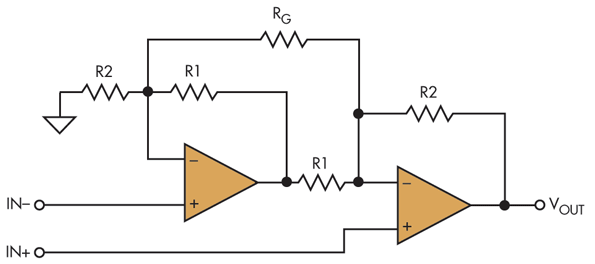
You must also consider consider the resistor noise, which is 85 μV p-p from 0.1 Hz to 10 kHz for the 1-MΩ resistor. If you’re measuring output load current, then this resistor represents an additional load. The three-op-amp loop also lets you measure I Q, but take care because of the 1-MΩ resistor at the DUT’s output, which becomes an issue because it’s always a parasitic load, regardless of which parameter you’re measuring. By carefully choosing a low-input bias current loop amp, the output current should cause an insignificant error. The two-amp loop accomplishes the zero output requirement by adding another amplifier. In this implementation, the output must be adjusted to the gained-up voltage offset V OS–not always an easy task–or the 50-Ω resistor in the above schematic would need to be switched out to eliminate feedback current. The self-test circuit isn’t the most efficient circuit for measuring very low quiescent currents because of the feedback current that the output must provide. Therefore, you must take steps to ensure that the output current is truly zero before making the I Q measurement. This current comes from the power supplies and it will add error to any measurement. That input voltage puts 15 ♚ through R f. The two-amp-loop circuit in Figure 1 puts a voltage of 750.75 mV on the output of the DUT (device under test).

The maximum input offset voltage is 750 µV. The maximum quiescent current for this part is 1-♚ per channel. To show you an example of these circuits, we tested the OPA369 op amp. These three circuits let you measure quiescent current, I Q. The feedback resistor R f actually can put a load on the part that can affect the I Q measurement.įigure 1. This includes feedback current in the test loop. Figure 1 shows the three practical circuits that can be used to test I Q and the other parameters, but it is essential to consider any load currents. Although an I Q test may seem rather simple, you must take care to ensure good results, especially when dealing with either very high or very low I Q parts. Quiescent current is the current a device draws with its output current equal to zero. You can use these circuits to test DC test parameters that include I Q (quiescent current), V OS (voltage offset), PSRR (power supply rejection ratio), CMRR (common-mode rejection ratio), and A OL (DC open-loop gain). These three topologies are 1) the two-operational-amplifier test loop, 2) the self-test loop, sometimes called a false-summing junction test loop, and 3) the three op-amp loop. Today, three test-circuit topologies are commonly used for bench and production testing of DC parameters in operational amplifiers.

Thus, a single test circuit no longer covers all DC measurements. At that time, a single test circuit may have been sufficient, but not today because modern op amps have far better specs. In January 1979, Electronic Test published an article claiming that a single test circuit that could “perform all the standard DC tests needed to thoroughly check any kind of operational amplifier” (Ref. Part 4, Testing op amps requires stable test loopsĪ version of Part 1 appeared in the Dec. Part 3, Configurable circuit tests op amps

Part 2, Test op amps for input bias current


 0 kommentar(er)
